Ceramic Capacitor Voltage Bias

Does The Capacitance Change When A Dc Voltage Is Applied To Ceramic Capacitors Are There Any Points To Be Aware Of Regarding Changes In The Capacitance Murata Manufacturing Co Ltd

Ceramic Capacitors Vs Dc Bias Derating Rule Of Thumb Misleading Electrical Engineering Stack Exchange
How To Derate A Ceramic Capacitor For Dc Bias Electrical Engineering Stack Exchange
The Voltage Characteristics Of Electrostatic Capacitance Murata Manufacturing Articles
How To Specify Bypass Capacitors Ee Training
Are Film Capacitors Affected By Dc Bias Electrical Engineering Stack Exchange
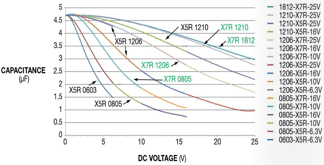
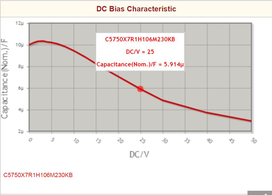
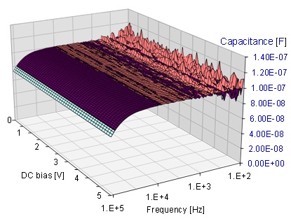
Figure 2 shows performance for a 10 uf 50 v 1210 capacitor.
Ceramic capacitor voltage bias.

Three Ways To Weather A Ceramic Capacitor Shortage Electronic Products
Resolved Lmr16030 Derating Of Ceramic Capacitors Must Be Considered Power Management Forum Power Management Ti E2e Support Forums

High Cv Mlcc Dc Bias And Ageing Capacitance Loss Explained Passive Components Blog

What Is The Reason That The Nominal Capacitance Value Cannot Be Obtained Murata Manufacturing Co Ltd

Mlcc Ceramic Capacitor Dc Bias Derating A Modicum Of Fun
Ceramic Capacitor Overview
Capacitors Part 3 Ceramic Capacitors 2 Electronics Abc Tdk Techno Magazine
What Are The Typical Esr Values Of Multilayer Ceramic Capacitors Murata Manufacturing Co Ltd

Benefits Of Using Mlcc Multi Layer Ceramic Chip Capacitor

High Cv Mlcc Dc Bias And Ageing Capacitance Loss Explained Updated Passive Components Blog

Capacitors Selection Guide Tech Notes Capacitors Tdk Product Center

Temperature Change Versus Ripple Current Of Ceramic Capacitor Module At Download Scientific Diagram
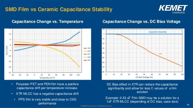
Smd Film Vs Mlcc
Dc Ac Bias Dependence Of Mlcc Capacitors Doeeet Com

Silence Of The Amps Noise Performance Of Ldos Depends On Filters Appendix Ee Times

Needed To Accomplish Different Tasks At
Power Tips How To Select Ceramic Capacitors To Meet Ripple Current Requirements Power Management Technical Articles Ti E2e Support Forums
Analysis Of Multi Layer Ceramic Capacitors
Https Encrypted Tbn0 Gstatic Com Images Q Tbn 3aand9gcrw6dzjyy5itwjx3ikino1byuzcuryil4 8iuusc36uanzj64hg Usqp Cau
How Much Capacitance Do We Really Get 2017 06 14 Signal Integrity Journal

Benefits Of Using Mlcc Multi Layer Ceramic Chip Capacitor

Gxm Series Murata Manufacturing Co Ltd

Edn Temp And Voltage Variation Of Ceramic Caps Or Why Your 4 7 Uf Part Becomes 0 33 Uf

This Forma Allows Creating Ceramic Capacitor By Electing Size Download Scientific Diagram
Source : pinterest.com
